

Departments of Transportation (DOTs) often utilize soil reinforcements attached to the back of abutment pile caps. The key principle behind this application is load-sharing between the piles and soil reinforcements, depending on structural displacements.
These applications are generally limited to conventional (non-integral) abutments founded on a single row of H-piles or prestressed piles.
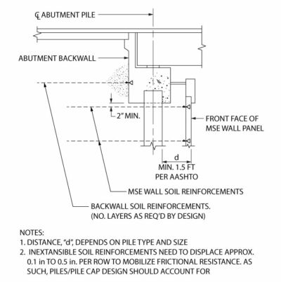
How the System Performs
Lateral loads from the bridge are shared by the backwall reinforcing strips and, to a lesser extent, the piles. Depending on the magnitude of bridge loads, the resistance of the pile cap reinforcing strips, and the stiffness of the piles, some pile deflection may occur.
Any pile displacement creates a cavity in the soil, allowing subsequent movement to occur without inducing additional lateral soil load on the MSE wall reinforcing strips below. This composite behavior results in most loads being carried by the backwall reinforcing strips over the service life of the structure.
Lateral Load Transfer to the MSE Wall Below
Initial pile deflection results in minimal load transfer to the reinforcing strips in the MSE wall below. Based on rough calculations, the lateral deflection of a conventional H-pile in service is less than 0.1 inch, and the potential lateral load transferred from the piles to the reinforcing strips is on the order of 200 lb./ft.
This load should not be included in the design of the MSE wall reinforcing strips below the pile cap, as the MSE wall design already accounts for traffic surcharge loads above the approach slab. Although the backwall reinforcements can be designed to resist the full complement of lateral loads, some consideration of lateral load should be included in the pile design.
Traffic surcharge loads are resisted by the reinforcing strips connected to the backwall rather than being transferred to the MSE wall below, which is already designed to account for a traffic surcharge component.
Design Assumptions and Considerations
The above behavior is based on a conventional abutment with a single row of piles and a maximum backwall height on the order of 12 ft. Multiple rows of piles add stiffness.
If the full complement of loads is specified to be resisted by the backwall reinforcements, the reinforcement design will be conservative.
Parameters Affecting Structure Performance
Several factors influence the performance of pile-supported abutments with backwall reinforcing strips:
- Spacing and stiffness of piles
- Backfill type (less lateral displacement with higher shear strength backfills)
- Rigidity of bridge bearings
- Magnitude of lateral bridge loads
- Clear distance to MSE wall facing
- Height of abutment backwall
- Type of approach slab and any potential stabilizing effect
- Settlement of foundation soils beneath the MSE structure
Mechanism of Load Transfer at Pile-Supported Abutments
The load-transfer mechanism develops as the abutment is constructed, backfill is placed, and the soil reinforcements mobilize their resistance.
1. Pile and MSE Wall Construction
Piles are installed, followed by construction of the MSE wall below the abutment.
2. Pile Cap Construction
Pile cap construction begins when the MSE fill reaches the bottom of the pile cap elevation. Attachment points (tie strip embedments) are placed in the pile cap/backwall.
Once the forms are removed, backfilling begins.
3. Backfilling and Reinforcement Installation
Backfill is placed in lifts and compacted up to the first reinforcement layer. Some lateral load is transferred to the pile cap and piles, and the soil reinforcements are installed.
Step by step, the abutment backwall is backfilled and the soil reinforcements are installed. Lateral movement is required to mobilize the frictional resistance at each reinforcement level, and a portion of the lateral load is shared with the piles.
4. Mobilization of Soil Reinforcements
A small amount of lateral movement at each reinforcement layer is needed to mobilize frictional resistance (0.1 to 0.5 inch depending on backfill type). While the reinforcements mobilize frictional resistance, a portion of the earth loads applied to the backwall are being applied to the piles.
Once the compacted backfill is in place, the soil reinforcements have been mobilized.
5. Resistance to Additional Loads
Additional surcharge loads and/or lateral loads transferred from the bridge through the pile cap are resisted through load transfer to the soil reinforcements. Additional movement of the soil reinforcements is minimal to mobilize additional resistance from the reinforcing strips.


